WHAT IS SBGN
SPECIFICATIONS
SOFTWARE
EVENTS
FAQ
HOW TO CITE
ABOUT
CONTACT
Learning SBGN
Examples
Reference Cards
Published Maps
Symbol Highlights
Figure to SBGN
Competition
Development Wiki
Process Description FAQs
- Should I always use straight lines for connecting arcs?
- Can we represent reversible interactions with a single association or dissociation glyphs?
- Should I always represent reversible reactions as two separate processes?
- Why must the inputs and outputs always connect to opposite faces of a process?
- Where should consumption edges of an association process meet?
- How can I represent multi-compartment reactions without multiplying the ugly compartment boundaries?
- Why can’t entity nodes overlap?
- Can I decorate my nodes?
- Should I always use state variables to represent covalent modifications?
Should I always use straight lines for connecting arcs?
No. SBGN Process Diagrams does not tell anything about the shape of the arcs. You can use straight lines, curved ones, or a mix of both. The two diagrams below are absolutely identical as far as SBGN PD is concerned.
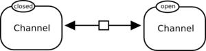
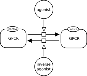
Should I always represent reversible reactions as two separate processes?
No. A reversible process can be represented by a single Process Node if this process is not modulated. The following process, representing the transition of a channel between open and closed state, is correct:
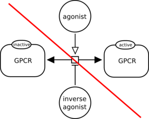
However, the following reversible reaction is modulated by two simple chemicals. One cannot understand which direction is modulated by each simple chemical. It is incorrect.
On the contrary, the following diagram is valid because the two directions are represented and the modulations are unambiguous.
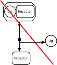
Can we represent reversible interactions with a single association or dissociation glyphs?
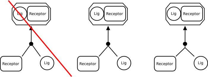
No. A dissociation glyph represents only the … dissociation, while the association glyph represents only the association process. The following is incorrect:
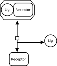
A reversible interaction must therefore be represented by separate association and dissociation processes. The following is correct:
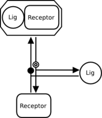
If there are no modulations on the association or dissociation, a reversible interaction can be represented by a regular process node, as follows:
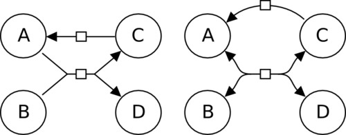
Why must the inputs and outputs always connect to opposite faces of a process?
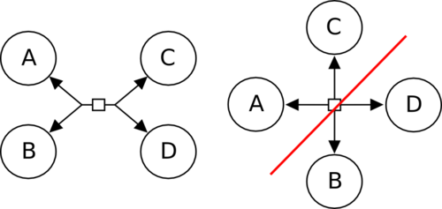
It is necessary to graphical separate the connection of the links leading to entities pools in two sets, corresponding to the SBML’s “reactants” and “products”, or the BioPAX “left” and “right”. The image below presents a reversible reaction transforming A and B into C and D, or the opposite. On the left, the connections are separated in two opposite groups, and the meaning of the reaction is clear. On the right, on the contrary, each edge is connected to a different face of the process, and one cannot understand which entity pools are transformed into the others.
Where should consumption edges of an association process meet?
The consumption edges should always meet in a single point outside the symbol representing a process. This rule applies for association as well. The point can be on the perimeter of the association symbol (center) or away from it (right).
How can I represent multi-compartment reactions without multiplying the ugly compartment boundaries?
All Entity Pool Nodes must belong to a compartment. It is possible to draw an EPN overlapping a compartment boundary, and software may provide magnet tools to implement that. However, the EPN always belong to the compartment containing the center of its bounding box. This is suboptimal, and for many biological processes, we want to use a true compartment to represent a membrane. The problem then is the multiplication of the boundaries. Indeed the membrane would have two boundaries, and each of the adjacent compartments another one. The resulting drawing is ugly, and actually misleading for the non-SBGN expert, who may be induced to think there are many more membranes than in reality.
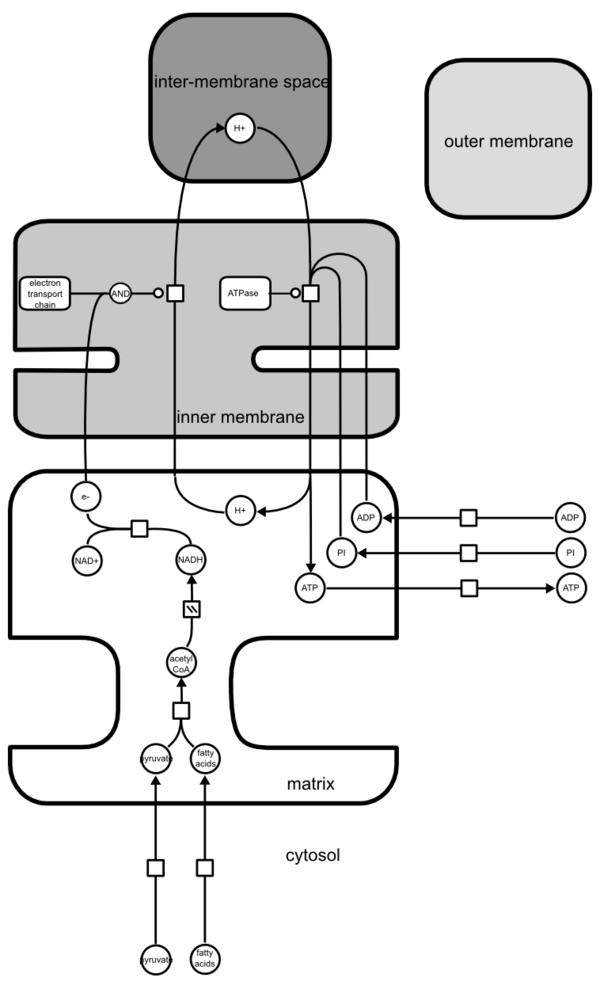
The trick is to use the fact that, in SBGN PD, compartments may overlap as far as no nodes or edges are hidden behind a compartment. The following image represents the conceptual view of the production of ATP by mitochodrion, as shown on figure 14-10 of Molecular Biology of The Cell, 4th edition.
However, while the map is conceptually fine, it is very hard to relate to the structure of the mitochondrion. But we can perfectly “stack” the compartments together, and draw the following.
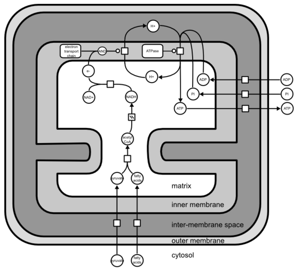
It is important to understand that, as far as SBGN PD Level 1 is concerned, the compartments are not CONTAINED into each other.
Why can’t entity nodes overlap?
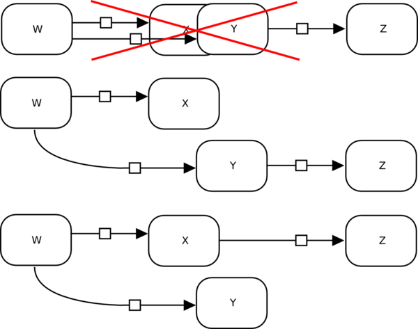
If entity nodes overlap, the edges connecting to them may become ambiguous, even when fulfilling the layout rule of placing edges above nodes. In the example below, W clearly produces X and Y, but it is not clear if Z is produced by X or Y.
Can I decorate my nodes?
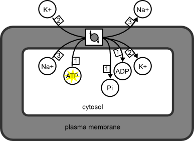
Yes! However, the decorations, not part of SBGN PD, will not modify the interpretation of the map. They are a kind of annotation. For instance, the following SBGN PD map represents the Na/K ATPase. The process node is decorated with the “usual” symbol for anti-porters. A yellow star signals that ATP brings energy to the pump. Those decorations are useful and informative for the reader. But they are not standard, and do not change the meaning of the map, which says only that 1ATP+3Nain+2Kout give 1ADP+1Pi+3Naout+2Kin. Furthermore these decorations may not be exchanged between different SBGN-supporting software.
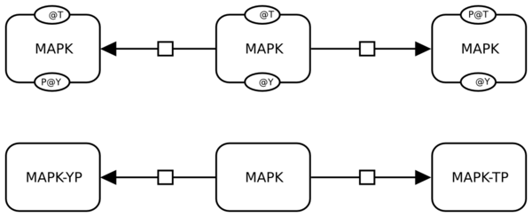
Should I always use state variables to represent covalent modifications?
No. As usual in SBGN, there is more than one way to do it, as far as your reader unambiguously interpret what you intend to convey. The figure represents the successive phosphorylations of MAP kinase. The top processes use state variables to represent the different phosphorylation sites. The bottom ones use different labels to represent the pools of non-phosphorylated and phosphorylated species. In the first case, one know that the differences between the entity pool nodes are phosphorylation because “P” is a reserved label for state variables. Because of the rules “once a variable, always a variable” (sometimes considered equivalent to the closed-world hypothesis), one must represent both state variables on each node, even if they are not affected by a process. On the contrary, in the second case, the only rule is that the labels must be different. As a consequence, one is not forced to mention the various sites in all labels. But one cannot know what the modifications are. “YP” is just a string.